Bill of materials (BOM) explained in brief
As long as I’m on a roll this month talking about balloons and how they work with the LogoPress BOM, I figured I might as well show you a few details about the LogoPress BOM and describe them. As mentioned below, there are many options making it very flexible and useful.
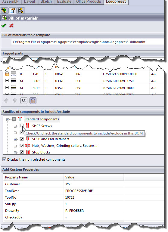
In the picture above, the first thing you see is the template being used at the current time. If you’d like to use a different template, simply switch it at any time.
The second thing you see is the list of parts, some of which are tagged (checked) to be in the bom and some of which are unchecked (the unchecked ones are not visible in the picture above). This list also shows you whether the part is locked or not, so it is shown as unchecked, checked or locked. This list also shows you, with both a graphical icon in the second column and a letter in the third column, which sub assembly this detail is in, be that the bottom, middle or lower.
The third thing you’ll notice is a button with a 1.2 on it and that button opens up the Number settings dialog, which is the one mentioned in the previous post that give you the options for balloon numbers, including which of the five organization methods you’d like to use.
The fourth thing is the padlock icon, and depending on which item or items in the list are highlighted may be available or grayed out if they are already locked.
The fifth thing in the list is a very nice feature – “Families of components to include/exclude”. In this picture above, you can see we have chosen to exclude the socket head cap screws from the BOM but have chosen to include the socket head stripper bolts and the pad retainers…
Finally, the last thing you see in the LogoPress BOM property manager screen shot above is the “Add Custom Properties” list. This is an awesome feature that we’ve added quite recently that allows you to automatically populate every single part file in your assembly with custom properties of your choosing in the list in a matter of a couple seconds. The files don’t get opened, they simply get populated with the data. Of course you want your sheet formats to include placeholders for these custom properties so that the title blocks are completely and automatically filled out with absolutely NO user intervention other than filling in these spots in this “Add Custom Properties” area shown above!
In the case of standard components, as you can see in the picture below, these are represented in the second column with a picture of the component rather than an icon showing which sub assembly they are located in as is the case with “plates” that are inserted in the die in the screen shot above. But as you can see below, in the case of a standard component where some are located in the bottom sub assembly and some are located in the middle sub assembly, (the Lamina bushings and the 1/2″ long button head cap screws) they are listed in both as is represented by the MB.
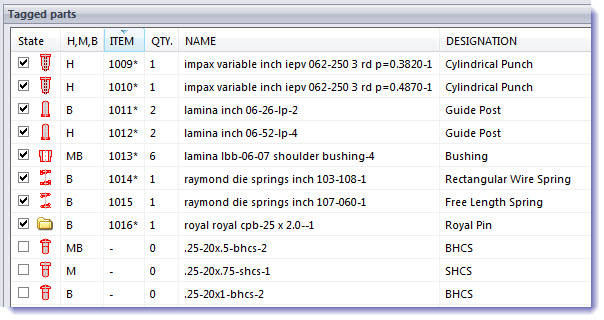
If you were wondering what the H, M, and B stood for in the column heading above, of course the M is Middle and B is Bottom – the H is Highest, which of course is the punch sub assembly.
Finally, some might be curious if the part numbers happen automatically as the part is inserted into the die – the answer is YES!
Topics
- -IMPORTANT-1- info for LP users
- -IMPORTANT-2- info for LP users
- LP 123GO Light
- LP 123GO Full
- LP How-To's for users
- LP Standard Components
- LP tips & tricks
- LP Unbending
- LP Warning messages
- SolidWorks tips & tricks
- General tips & tricks for all
- Windows tips & tricks
- A great use for WAX (stretch webs)
- Computer performance
- Computer benchmark
- Software we use
- FREE software
- Uncategorized