Logopress DieDesign PREMIUM
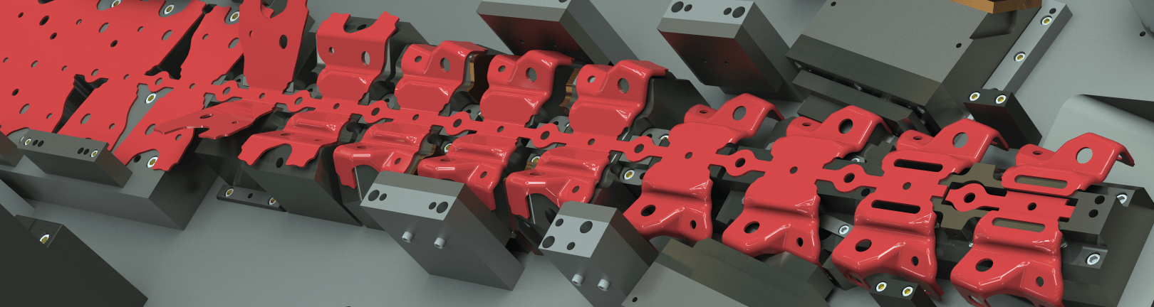
Logopress—with over 30 years of die design software development and feedback from customers—builds upon SOLIDWORKS, adding all the necessary tools and options that die designers need to help automate the die design, debug and build processes. Logopress DieDesign software provides a mature and systematic workflow for tool design—with a special focus on die design—while adding consistency between designs and designers. Logopress makes die design in SOLIDWORKS economical, fast and efficient—while at the same time practically eliminating mechanical debugging.
Logopress DieDesign PREMIUM is an all-inclusive, turn-key package for all aspects of complex die design. PREMIUM expands on the standard DieDesign software by adding a number of partial unforming tools to help produce the intermediate stages of complex, double curved, and other automotive, electrical, and medical style parts. ProgSim can be added to either of these packages (DieDesign or DieDesign PREMIUM) to provide sheet metal forming simulation capabilities to prove that your design will work when steel is finally cut. Everything on this page is included as part of the DieDesign PREMIUM package.
View Product Matrix
| Flatten | StripLayout | DieDesign | PREMIUM | |
| ProgSim - Integrated Incremental Forming Simulation, powered by the AutoForm solver | optional | optional | ||
| Unbend parts in steps or in a single step | X | X | X | X |
| Partial unbending - Moved center and Fixed center | X | X | X | X |
| Overbending to compensate for springback | X | X | X | X |
| Flatten thin-walled extrusions | X | X | X | X |
| FEA Flatten complex organic shaped stamped parts | X | X | X | X |
| % of thinning, thickening, stress and strain analyzed | X | X | X | X |
| Faces merging - imported surface from selected faces | X | X | X | X |
| Offset faces - offset or thicken surfaces that SW cannot | X | X | X | X |
| Extend faces - extend faces of a surface that SW cannot | X | X | X | X |
| Round Draw Part - automatic creation of drawn stages | X | X | X | X |
| Round Draw Part strip creation with stretch webs | X | X | X | |
| Strip Layout - Automated creation of a strip assembly | X | X | X | |
| Strip parameters managed from the property manager | X | X | X | |
| Automatically adds a project number to file names | X | X | X | |
| Nest parts to find best material usage | X | X | X | |
| Add/remove parts and stations | X | X | X | |
| Splines in the blank geometry detected and highlighted | X | X | X | |
| Splines within a sketch are converted to lines and arcs | X | X | X | |
| Manage creation of cutting punches and cuts in strip | X | X | X | |
| Manage creation of form punches (5 types) | X | X | X | |
| Creation of punch mismatch/bypass notches (3 types) | X | X | X | |
| Add shoulders/heels/pedestals/shear to punches | X | X | X | |
| Strip note - estimating data exported to spreadsheet | X | X | X | |
| Cutting and forming forces computed and displayed | X | X | X | |
| Costing tab displays material costs (part/scrap/punch) | X | X | X | |
| Part Nesting - nest parts or bodies of a part | X | X | X | |
| Tool Structure - Automated creation of a tool assembly | X | X | ||
| Create tool from a template or create a blank tool | X | X | ||
| Manage insertion of plates and creation of mates | X | X | ||
| Manage plate properties material/treatment/descr. | X | X | ||
| Automatic creation of drawings (multiple methods) | X | X | ||
| Filters - display any combination of U/M/L sub-assy | X | X | ||
| Add an Insert - insert, opening, and shim (optional) | X | X | ||
| Punch Mounting - creates openings in plates | X | X | ||
| Sketch Fillet Management - corner clearance tools | X | X | ||
| Standard Catalog Components (200,000 +) | X | X | ||
| Custom Component capability (created by user) | X | X | ||
| Machining Axis - series of holes and/or components | X | X | ||
| Automatic Pattern - place and dimension sketch points | X | X | ||
| Standard Component Copy | X | X | ||
| Hole Library - Dozens of hole types not included in SW | X | X | ||
| Wire EDM Start Holes (recognized in LP hole tables) | X | X | ||
| DIE DEBUGGER - Motion Simulation of die in press | X | X | ||
| DIE DEBUGGER - Dynamic Interference of die in press | X | X | ||
| First Hit Optimizer - visualize first hit location | X | X | ||
| Slug Clearance Detection - checks for missing slug holes | X | X | ||
| Create an exploded view at any point of the press cycle | X | X | ||
| Enhanced hole tables (recognizes nonstandard holes) | X | X | ||
| Full and Compact hole table types | X | X | ||
| Smart Ordinate Dimensions - auto dimension all holes | X | X | ||
| Bill of Materials - manage part properties and detail # | X | X | ||
| Automatically determines the stock sizes of parts | X | X | ||
| Detail # and quantity values in custom properties | X | X | ||
| Save as with new project name | X | X | ||
| Progressive Blank Companion - partial unforming tools | X | |||
| Unforming or partial unforming complex shapes | X | |||
| Pseudo unbending | X | |||
| Unforming up to surface | X | |||
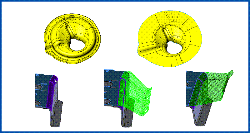
Partial Unforming Tools
Includes a collection of tools for partially unforming a part that contains double-curved geometry. In many cases, these tools help to dramatically speed up the creation of the intermediate stages of the part that will get progressively formed. Learn More
The rest of the items listed below are all included as part of both DieDesign packages.
The StripLayout and Flatten modules can be purchased separatelyfor users who do not need to design dies, jigs, fixtures, or other special machines. These smaller packages can be incredibly useful for anyone in the quoting role.
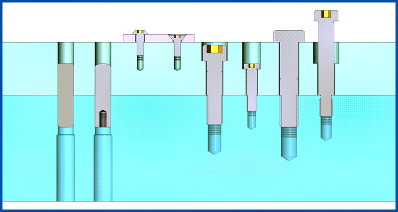
Intelligent Catalog Components
Insert everything from screws to nitrogen, including the correct part number, mounting hardware, and clearances in just a few clicks. Over 200,000 individual components to choose from. Never misalign a hole again. Learn More
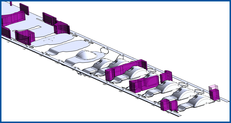
StripLayout
The StripLayout module can be used for both progressive dies and for transfer dies. It allows quick modeling of a true 3D strip in a very easy and logical way. Learn More
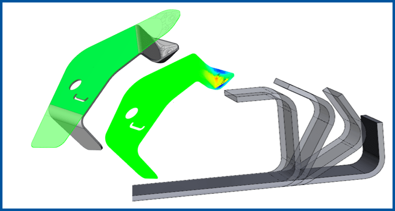
Flatten
Unbend parts incrementally to generate the stages of forming. Includes one-step Finite Element Analysis to quickly assess formability of parts. Learn More
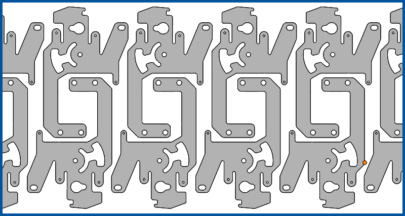
Nest
Developed to optimize material usage in a strip layout, this tool can also be leveraged for nesting parts in a sheet, such as for a laser, or punches into a block for WEDM. Learn More
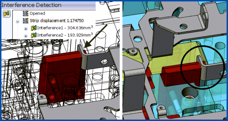
DIE DEBUGGER™
Put the tool into motion, and check for interferences dynamically as the press cycles and coil feeds. Catch design flaws early in the process! Watch Now
Beyond the systematic workflow, Logopress provides a number of tools to optimize SOLIDWORKS for die designers. These items are included exclusively with the Logopress DieDesign software packages. This functionality may not be as groundbreaking as some of the above tools, but are the little details that take the product from 'good' to 'great'. After all, this is software for die designers, created by die designers.
See it in action:
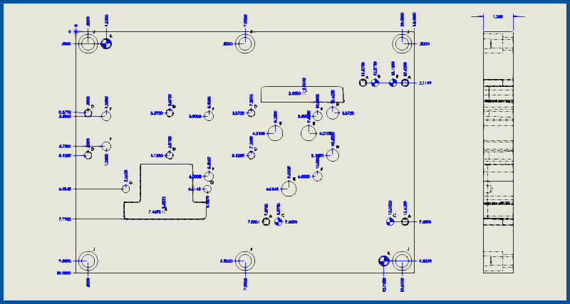
Improved 2D Drawings
(47:55) SOLIDWORKS drawings are significantly enhanced with Logopress “Tool & Die” Hole Tables, Logopress Smart Ordinate Dimensions, Logopress “Bill of Materials” (BOM) and multiple methods of Automatic Drawings Creation. Play Now
Tool Structure
(1:00) Tool Structure is the interface where the plates and assemblies of the die are assembled. Some of the tools included are: insert/delete plates, manage custom properties of plates (populating the BOM), manage mates, change plate dimensions and user defined project name (job number) automatically added to file names. Play Now
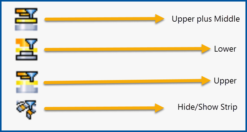
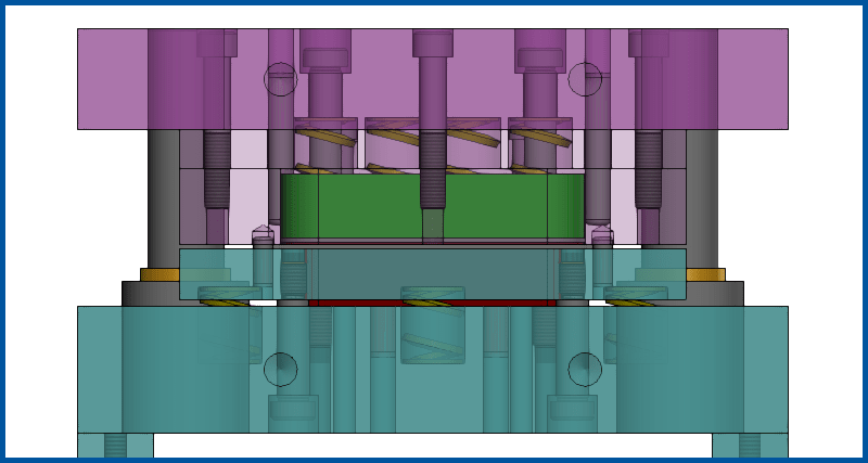
Filters
(0:37) Easily display any combination of the upper/middle/lower sub-assemblies by clicking on one of the Logopress filter icons. Toggle the strip assembly between hidden or shown with a single click. Play Video
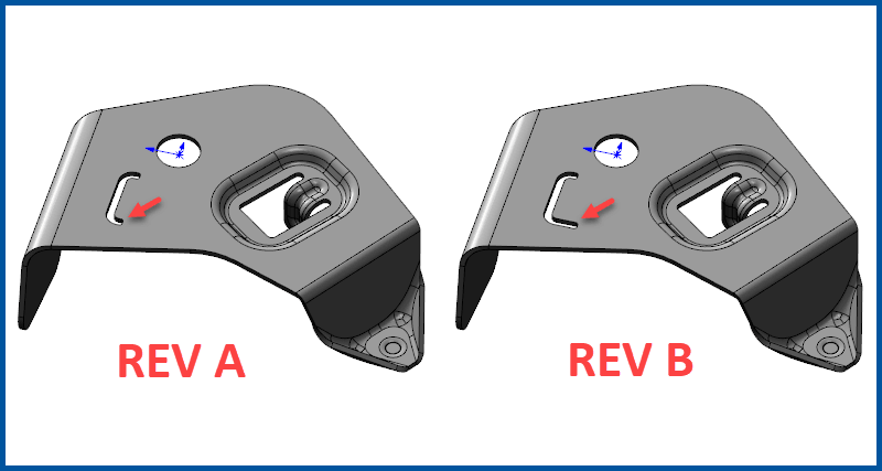
Save As... With New Project Name
“Save as with new project name” is used to create a new and completely independent copy of a tool assembly (including all parts and drawings), allowing the user to create a completely new and independent die design from the first in what is oftentimes a small fraction of the time it took to design the first one.
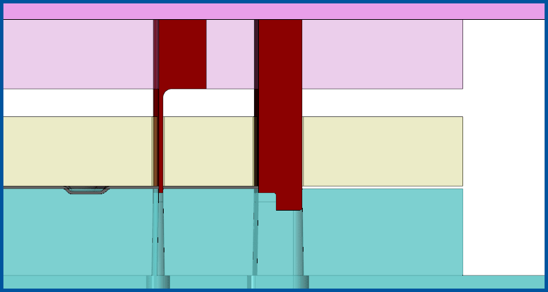
Punch Mounting
(1:13) Punch mounting “mounts” the punches that are in the strip assembly into the upper tool assembly and automatically creates the openings with clearances in the appropriate plates. The mounted punch and the related plate openings can be easily and quickly deleted by selecting it and clicking the “delete” option. Play Video
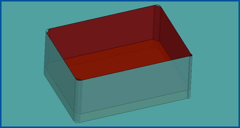
Die Inserts
(1:41) Logopress Add An Insert will quickly create and add an insert into a tool assembly, along with the opening in the plate. A shim under the insert is also optional. The opening can go all the way through the plate or a pocket at a desired depth can be created. Two modes are available, Part Mode (created from scratch) and Split Mode (split from existing geometry). Play Video
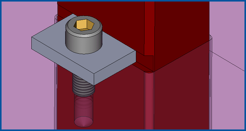
Punch Locking Tabs
(1:28) Various sized and shaped locking tabs can be automatically created along with simultaneously adding the groove in the punch as well as the screw and the tapped hole. Play Video
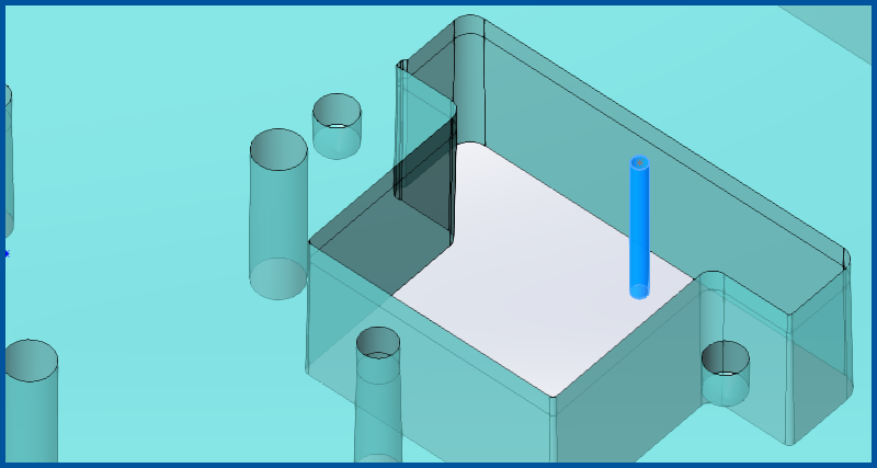
Wire EDM Start Holes
(1:04) Start holes can be created through a stack of several plates all at once or through a single plate. Logopress Hole Tables recognize wire EDM start holes and call them out as such. Five different types of wire EDM start holes can be created depending on your CAM system requirements. Play Video