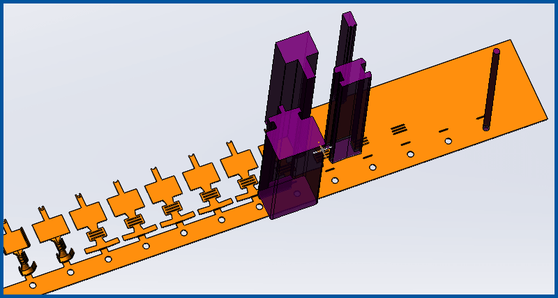
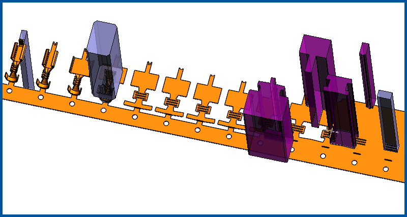
2020 Box Terminal Strip Layout
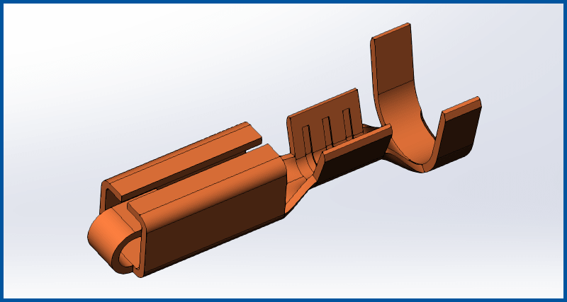
Redone in LogoPress 2020: Complete LogoPress Strip Layout of a box terminal in a bit over an hour, including overbend and springback management, coined areas on terminal (easy to do and convey using a solid strip as LogoPress does), demonstration of ability to overlay various stations on top of one another, and creation of a complex 3D form punch.
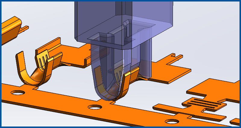
(7:48) In this first video we start getting the part ready to put into the strip layout and start adding Station Marks. We use LogoPress BLANK along with the "Split Line" command to flatten the part symmetrically to determine how much material the lofted offset takes. The body of the part is then split into multiple bodies using the "Split" feature so that the linear bent areas can be accurately unbent using LogoPress Unbending independent of the lofted areas. A "Split Line" is added to the 180 degree radius to break it into two different radii and then springback/overbend is applied to this leg, bending it from 180 to 185 degrees and automatically remodeling the radius to the new correct size to allow for the same material after springback and so that the radius is the correct size after springing back.
(14:07) More Station Marks are added, the box is laid open and a new loft is created so that the part is accurately represented before adding the Station Mark for that station.
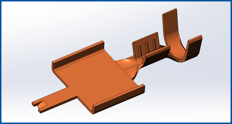
(9:12) The final two bends in the box are unbent so that the box is now flat and its solid body is moved away from the original loft. The center solid body that is the wire crimp area is accurately unbent while retaining the wire crimp coin areas (because we used the "Unbend the solid" option in unbending) and its body is moved into position. The part is fully flattened other than the coined areas which remain.

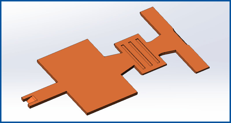
(6:27) The coined areas are removed so that the part is fully flat and the last Station Marks are added. The LogoPress Annex part is created and then we realize we forgot to add the small corner radii fillets to the flat blank that the part will require for manufacturability (WEDM corners). So we return to the reference part and roll back to before the final Station Mark that is named 150 FLAT and add our fillets and then roll back to the end and Ctrl+Q to force the rebuild of Station Mark 150 FLAT. We then return to the Annex part and use the LogoPress command “Update the stations of the Annex part used in the strip” and then the radii we just added show up on the Annex part 150 FLAT configuration.
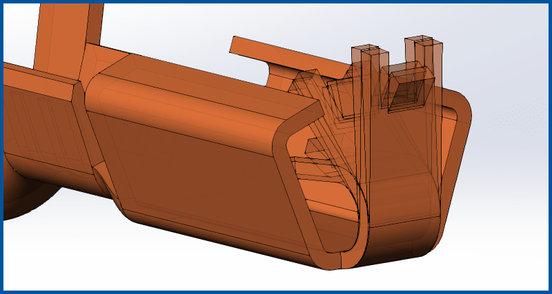
(2:27) Here we don’t do any specific work on the strip layout or the part, but simply demonstrate the very important and extremely useful LogoPress command “Show or Hide the imported bodies”. This allows the designer to see how the individual stations overlay on top of one another before putting the part into a strip layout.
(12:18) Now that the more difficult part of getting the part ready is completed, we move on to the much simpler and more automated creation of the actual strip layout assembly where we set the distance between parts, the progression, the distance from the edge of the part to the front and to the back of the strip edges, see the feedback regarding material usage percentage, etc... This step also includes the semi-automated modeling of all of the cutting punches using the ever-popular “Search the punch outline” to help create the punches.
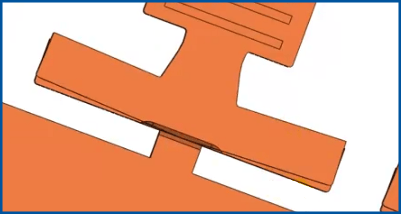
(7:09) Whenever a stamping has a coined area extending up the edge of the part (such as this part has at the cutoff carrier area with the V-notch coin) there’s a strong chance that the coining takes place before trimming in order for the trim punch to cut through the coined area. This means that the coined area needs to extend beyond the part and into the skeleton/carrier. In this video we show how to extend this coined area into the skeleton and we also move a punch from one station to another using drag-and-drop.
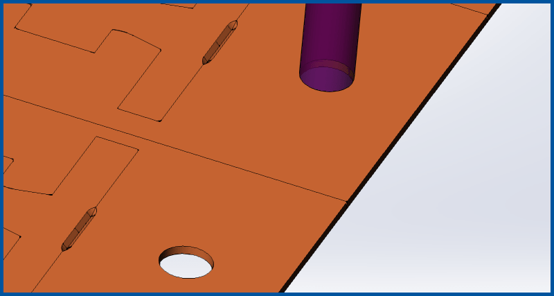
(19:25) In this final video we create the complex 3D form punch, taking advantage of the LogoPress Faces Merging command to simplify the surface used to cut this punch shape. We go on to create a forming punch with a “set radius” or “kill radius” for the 90 degree bend up. The automation of the LogoPress “Shoulder/Heel/Roof/Pedestal” command is then demonstrated as we add a T shaped shoulder to one of the cutting punches. Finally, we add a custom note along with a custom tonnage to the complex form station that will get included in the automatic tonnage calculation that LogoPress performs and the LogoPress strip information note is reviewed.
----------BONUS VIDEOS BELOW----------
We were asked by a customer to show how to edit this strip, taking it from the "roughed in" and simplified estimating stage (as demonstrated in the videos above) to a point where it would eventually be ready for tooling. So the videos below show some editing of the strip layout created above, including adding mismatches as well as editing the part to show a less simplified and more accurate flat blank in the large crimp end area.
(9:35) The main edits are done on the Reference part where we change several things in the tree so that the flat blank, particularly the crimp end, is accurately represented. After the Reference part is changed, we switch to the Annex part and it is quickly updated using the LogoPress command "Update the stations of the Annex part used in the strip". We toggle over to the strip assembly and it can be seen that this has also updated, but requires some editing or replacing of three of the punches.
(6:28) We replace the "Dangling references" found in the sketch of one of the punches and delete and replace the other two punches, adding mismatches to one of them. The station labels are then edited in order to demonstrate how to turn them on an angle, or make them horizontal rather than vertical. We also show how to avoid truncating the text of the labels. The LogoPress option for cutting punches called "Cut the part" is demonstrated in order to cut the mismatches into the Annex part which is used in the strip assembly.