Stampack Videos
Search
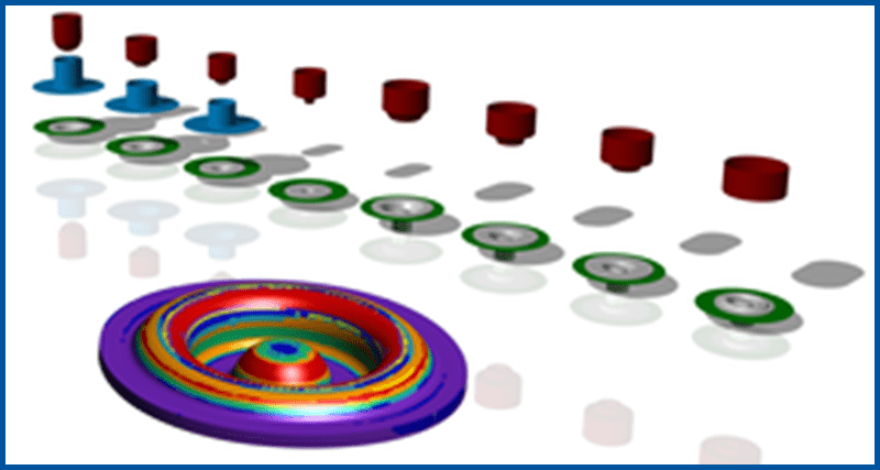
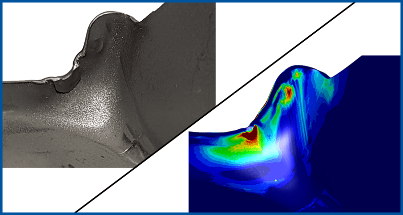
Drive Disk
(1:28) This is a multi-stage deep drawing process of a thick circular blank in a manual insertion tool. And the process indeed showed a big problem in OP30: A crack in the part, more precisely a bottom tear! Play video
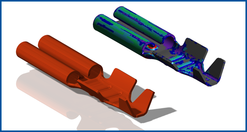
Blade Receptacle
(0:57) In this example you can see the typical optimization process required to produce stamping parts for the electric industry. In OP20 the original design led to an edge crack. In OP40 a minor error in the tool design led to a wrong blank shape after the forming that caused a crack in OP60. Play video
Thick Bracket
(0:22) An example of the benefits of a full SOLID simualtion. Play video
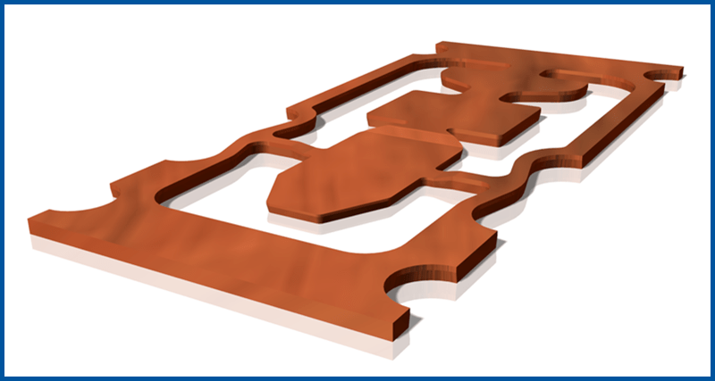
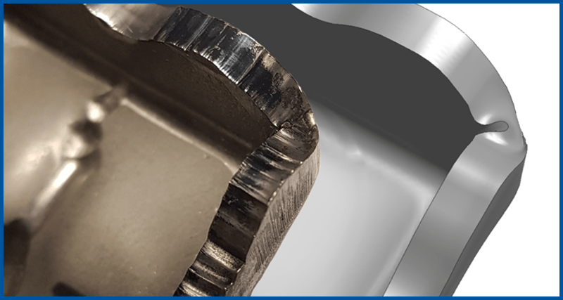
Coining Example - Flat Plug
(0:54) Coining of small copper parts is extremely challenging due to an unpredictable material flow in combination with extremely small tolerances at the outline. In this example you can see the typical optimization process required to produce coining parts for the electric industry. The challenge is to be in tolerance with deviation up to 0.025mm. Play video
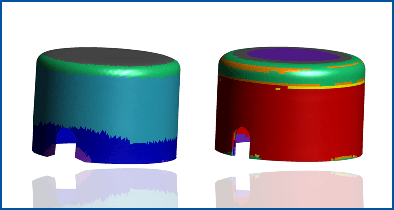
Solid: Tolerances
(0:58) A key question for the tool designer is the question of tolerances. Are we in tolerance when we go to production? Performing a virtual try-out in Stampack, the tool designer himself checks the tolerances before the tool is constructed and without the need of any tryout on the press. Play video
Solid: Solving Process Issues
(1:24) The Solid simulation precisely predicts Blank markings by tool contact, Surface distortions, and compression of edges Play video
Shell: B-Pillar
(0:16) Quickly determine the formability of a part, even big ones! Play video
Shell: Edge Crack
(0:23) A quick simulation of edges slitting during a form. Play video
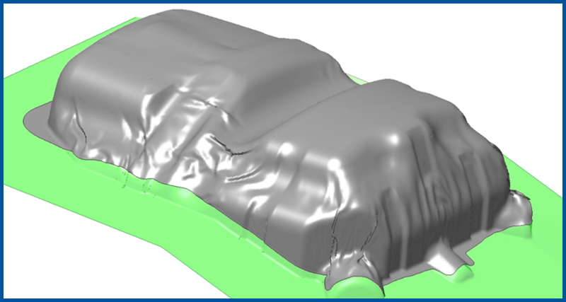
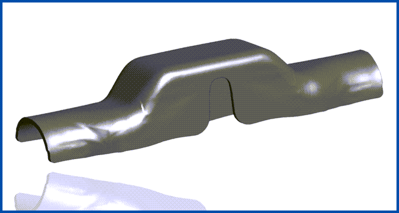
Thin Shell - Wrinkles and Cracks
(0:22) Producing heat shields for example for covering the exhaust system in a car is extremely demanding. Due to very small sheet thicknesses and low holding forces wrinkling is unavoidable, but wrinkles need to be in strictly controlled positions. Play video
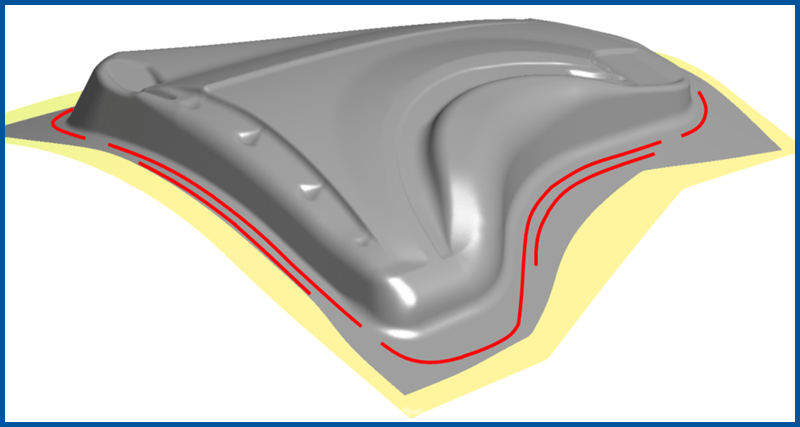
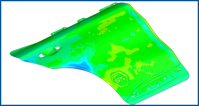
Fender with Drawbeads
(0:43) In Stampack, a drawbead can be simulated with a positioned line and an equivalent drawbead model in the background to reach a massive speedup compared to geometrically modelled drawbeads in the tools. Play video
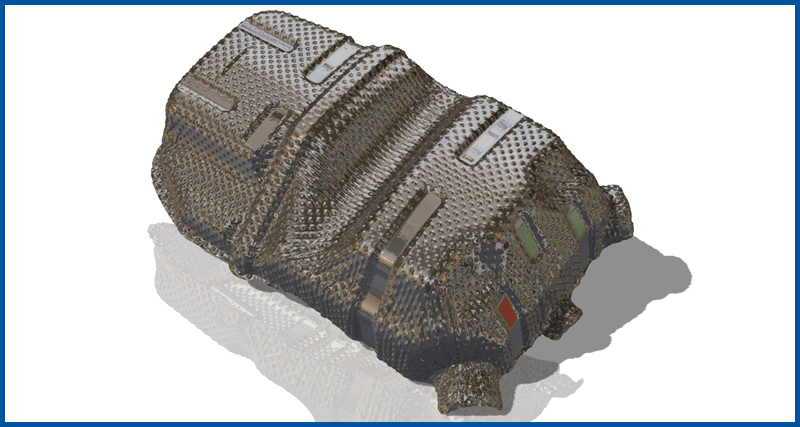
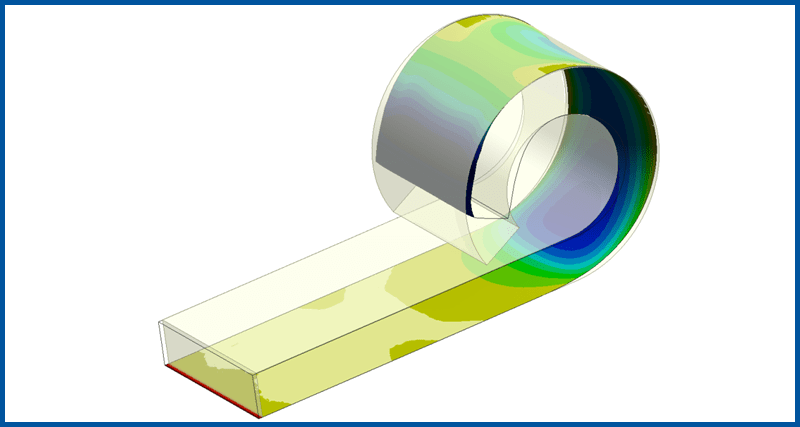
Embossed Heat Shield
(0:47) Typically heatshields and sound absorbing blanks are made with extremely thin and especially prepared blanks, the so-called embossed blanks that have a non-flat initial surface. Stampack handles this with ease. Play video
Shell vs Solid: Shear Fracture
(0:37) The industry-standard 'shell' type simulations cannot tell the whole story. Play video
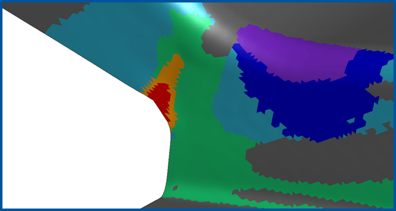
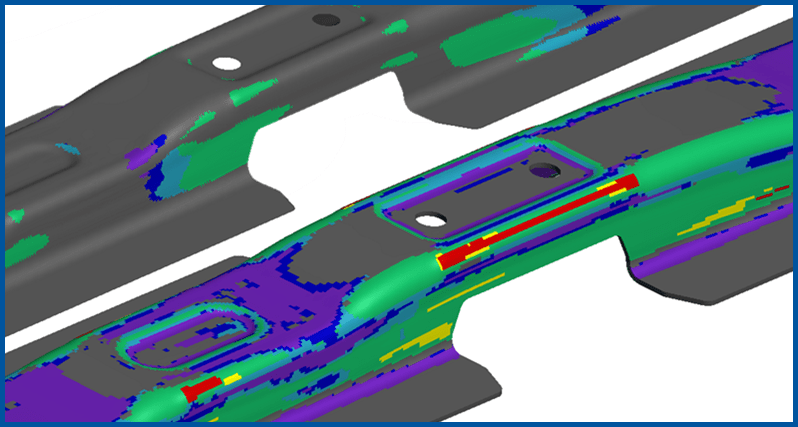
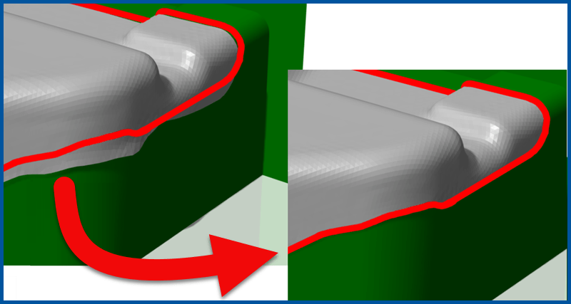
Shell vs Solid: Blank Marking
(0:52) The video shows the forming of a cable cover part with problems on the surface simulated by Stampack. It is a progressive die part and can be manufactured without failing. In the first stage, you can see a strong surface defect, where a small tool radius has caused a dent in the part (2nd last picture). Play video
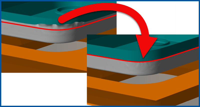
Shell vs Solid: Thickening
(0:39) A typical situation in sheet metal forming is the compression of the thickened zones of the sheet when the press closes. Within this event material is compressed with a lot of force resulting in huge and uncontrolled stresses that have massive consequences for the springback behavior. However, due to non-physical contact shell simulation fails to show compression due to contact pressure. Play video
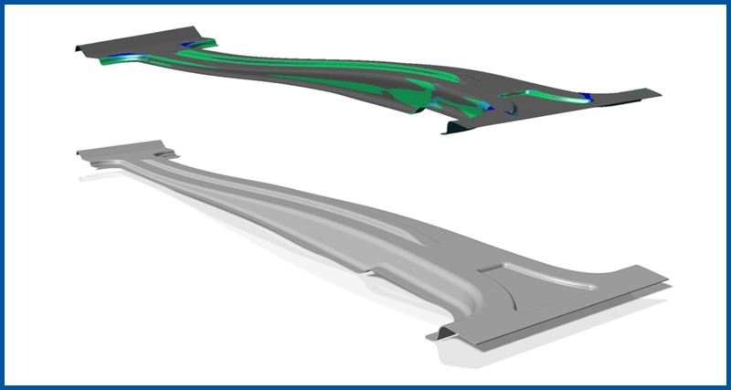
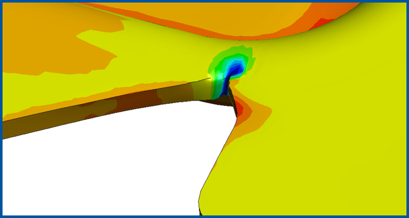
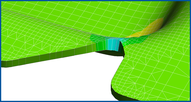
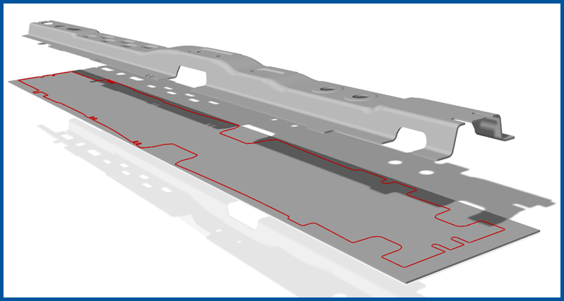
Solid vs Shell: Bending Failure
(0:34) In this simulation of a crossmember made of high strength steel, the toolmaker felt safe after good results in a shell simulation. But in the real process, the part cracks all over the bending radius! For brittle high strength steels, the cracked outside leads to a material weakening, so the crack propagates through the component. Play video
Fast Solid
(1:06) Solid simulations can still be fast! Play video
Trim Optimizer
(0:33) Obtaining optimal trimming lines is an essential part of modern method planning. In daily practice the approximated trimming line coming from CAD are quite good, but usually they're not in tolerance yet. Instead of making difficult and costly correction loops in try-out, do it on screen! Play video
Trim Optimizer with Wrinkles!
(0:27) Stampack's powerful trim optimizer algorithm is powerful enough to handle wrinkles and other tough geometry Play video
Trim Optimizer: Blank Shape
(0:26) Trim geometry is optimized in the shell solver. Play video
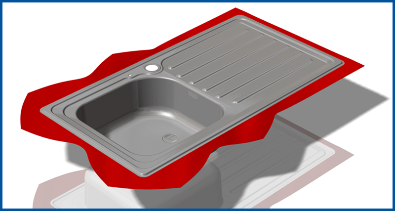
Trim Optimizer: Waste Reduction
(0:44) In this deep-drawing of a kitchen sink, we started with a blank chosen by the tool designers experience on comparable projects. In 4 automatic trim optimization loops, we converged to the optimal blank. As you can see, the result is amazing! Play video
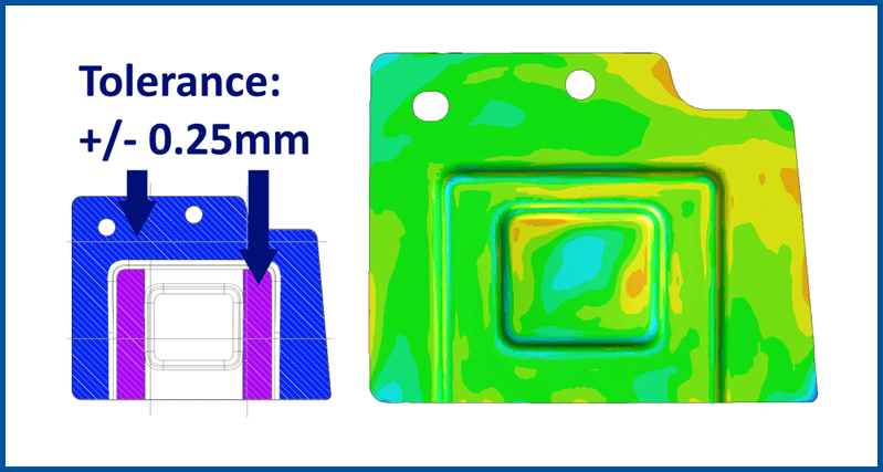
Springback Compensation: Pengfei GmbH Germany
(1:20) Feasibility of a sheet metal part is not sufficient to get good parts. In what follows we see how the engineers of Pengfei GmbH Germany hold a ±0.25mm tolerance in a rear wall panel on behalf of Buschhoff Stanztechnik by applying Springback compensation and Trim Optimizer. Play video

Springback Compensation: Remove Undercut
(1:24) One of the biggest challenges in the compensation of springback is to avoid undercut in vertical walls, which typically arises when we simply compensate in the reverse direction of springback. To overcome this issue Stampack introduced an automated filter that allows the software to compensate as much springback as possible without allowing undercut surfaces. Play video
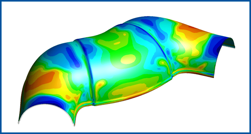
Springback Compensation: Half Shell
(1:17) Another example of compensating for springback while avoiding undercutting. Play video
Springback Compensation: Strict Tolerances
(1:22) One of the biggest challenges in the automotive industry is to make sure that parts are in tolerance. To counter springback it is mandatory to reduce springback in the first place by introducing stretch in the part without introducing failure. Play video