Real Time Die Designs
The goal of this video is not to prove that we can create an average die design in 5 hours. Of course this is a very simple part and we planned all that we did and we practiced all that we did before creating the videos. Our goal is to show the entire process, method and philosophy of LogoPress Die Design software in order to illustrate its ease of use, its efficiency and how…
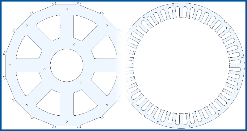
Starting with the 3D model of the part, a strip layout for this Stator and Rotor is created in less
than 20 minutes, including all cutting punches. Starting with a very
basic tool template, the die is then created. Standard catalog components, including pierce punches, are added and clearances are cut through all plates. The BOM and a detail drawing are created…
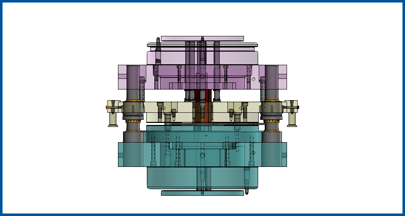
Complete fineblank die design starting from an imported part file through to part drawings and bill of materials in under an hour.
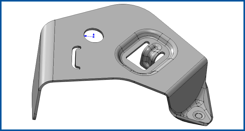
A parasolid part is imported, unformed to create a flat blank, and then a two station tool created around it in about an hour and a half, including 2D drawings. Also watch a simulation of the part being flipped and transferred between stations using LogoPress Die Simulation.
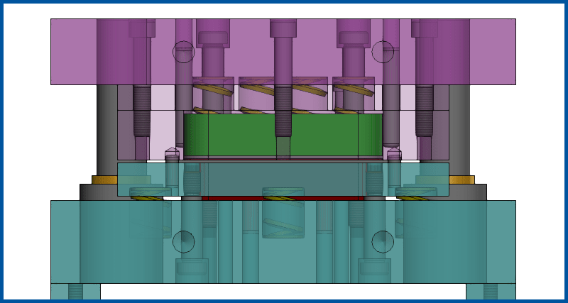
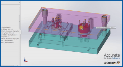
This is a walk through of LogoPress providing step by step instructions for creating a single hit, compound blank and pierce die. This design uses springs, rather than knockout pins for extracting the part.
This video series is well over a decade old. The look of the software has changed over the years, but the robust design methods still hold strong.